
How to Check Laser Weld Penetration Depth: 5 Methods Compared
Short answer: Before asking whether weld penetration is “OK”, define it: target depth, tolerance, measuring positions, and sampling or 100% inspection. Five methods are common: metallographic cross-sections, tensile/shear tests, X-ray/CT and ultrasound, post-weld 3D vision, and in-line OCT depth monitoring. Use metallography for process development and first articles; in production, OCT for depth plus 3D vision for appearance on every part, with periodic sections to re-check.
First, write down what “OK” means
- Target depth and tolerance, e.g. “at least 0.3 mm into the lower sheet”.
- Where to measure: start, middle and end of the seam.
- Sampling rate, or 100% inspection with stored data.
- What happens to NG parts: alarm, reject, trace back to which batch.
Put these into the technical agreement; only then can any method give a clear pass or fail.
Five methods compared
| Method | Destructive? | Every part? | What it shows | Best used for |
|---|---|---|---|---|
| Metallographic cross-section | Yes | No, sampling only | Depth, width and fusion at the cut; the accepted reference | Process development, first articles, periodic checks |
| Tensile / shear / peel test | Yes | No | Strength, not depth itself | Strength validation of overlap and spot welds |
| X-ray / CT, ultrasound | No | Hardly — slow and costly | Internal pores, lack of fusion; CT can reconstruct depth | Offline sampling, failure analysis |
| Post-weld 3D vision | No | Yes | Weld width, misalignment, spatter — not depth | 100% appearance check, together with a depth method |
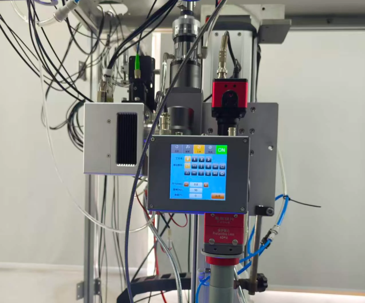
| In-line OCT depth monitoring | No | Yes, during welding | A depth curve along the whole seam | 100% depth judgement in production, after calibration with metallography |
How close is OCT to metallography?
We compared them on 0.8 + 1.5 mm copper overlap welds: 5 power groups from 1500 W to 2300 W, 8 samples each, sections at 2, 4, 6 and 8 mm along the seam against OCT readings at the same positions. The mean absolute percentage error (MAPE) of the five groups was 2.07%–5.09%, largest in the 1900 W group.
- These results apply to these samples and this process only; they are not a general accuracy of the equipment.
- The deviation differs between power ranges, so one fixed offset cannot cover all parameters; calibrate per material, plating, joint and process window.
Full test design and data: OCT Weld Depth Monitoring System.
A typical production setup
- Process development and first articles: metallography sets the parameter window and depth target.
- Production: OCT measures depth and 3D vision checks appearance; a part passes only if both are OK, NG parts are rejected automatically and logged.
- Periodic checks: section parts per batch or shift to confirm the OCT calibration has not drifted; re-check after changeovers or new material.
The most common mistake: not measuring the same spot
When comparing OCT with metallography, if the OCT value is taken at a different position from the section, the natural variation along the weld is mistaken for measurement error. Define the measuring points in the test plan, and make sure sample numbers, depth curves, section photos and value tables match one to one.
We can run a weld depth sample test on your parts: the same batch gets OCT depth curves and metallographic sections, compared in one report, before you decide how to inspect in production. Free sample test · 3D weld seam inspection · WhatsApp +86 186 1631 3040
Post a comment